
Undoubtedly the closest neighbor to heat are the light particles. In sunlight, heat and light are interacting hand in hand, and even in spectroscopy, heat and visible light are close neighbors. As mentioned in the discussion of heat, heat particles are material particles that in both free and combined state can occur according to the principle of A & B. The same is true of light, that is, light composed of material particles (the particles with different colors differ from each other) which exist in free form and in combination with different materials. The free form causes the visibility of objects and can effect rod and cone cells. They also have properties such as velocity, speed of c in vacuum, reflection, refraction, diffraction, interference, etc.
In the combined state with other material particles, light material particles can be in the silent or latent state according to the principle of A & B. They can reversibly be released from their constraints and become free particles with their original optical properties. Isaac Newton, probably the most authoritative proponent of the particle theory of light, turned out to be unsuccessful in defending the particle theory of the light at the time. The wave theory of light has rejected his original interpretation of particle theory of light mainly because some observations could not be explained by the original particle theory. Many same observations remained unexplained by the same wave theory and currently can only be explained by photon particles, which in a way is reversion to the semi material nature of light.
If it would be possible to interpreted and explained all known optical phenomena with particle theory in an acceptable way, it can be claimed that an effective step has been taken in the theorizing of physics. At the same time if material particles of light can be sufficient in explaining light phenomena, the same methodology can be used towards explaining the behaviors of other photon particles.
The material particle definition of light
Light is a material particle with defined and specific mass and volume depending on the color. Within visible light spectrum for example, the volume and mass of red-light particles is larger than other spectral lights. One of the interesting properties of these particles is their high velocity in vacuum and clear environments. The cause of this high velocity is unclear and seems to be an inherent property of all particles that have extremely low mass such as heat or light particles. A simple argument for saying that the high velocity of light particles is an intrinsic property lies in the fact that when light enters a transparent medium from a vacuum, such as glass or water, it slows down, and when it leaves a transparent medium, it regains its initial speed again.
Needless to say, these proposed light particles are quite different from the photons of light (zero stagnation mass). In simpler terms, the zero-stagnation mass of matter does not make sense. The laws of light reflection dictate that we consider light particles to be spherical and elastic, and because these particles have a high mass and velocity (3x10⁸ meters per second), then we expect that each particle of light has a certain linear motion proportional to its mass. Light particles have a continuous spectrum whose particle sizes are different and as a result the size of their linear motion is also different from each other. We will discuss this difference in mass and the size of the linear motion and its consequences shortly after.
Considering the extremely high velocity of light particles and the weak linear motion it reveals at the same time, it can be concluded that the mass of light particles must be extremely small. Another point to note is that light particles, as long as they are not placed in a strong gravitational field, will move in a straight line. They change direction only when become object to a strong gravitational field.
Optical phenomena like reflection and refraction within transparent environments or the behavior of light particles when passing through narrow gaps (brush and interference) are all dealing with the structure of matter (mostly solid and liquid). Therefore, before discussing these optical phenomena let us try to reach an approximate agreement on the structure of transparent matter and media.
The structure of crystalline transparent and solid environments
There is a consensus on the structure of crystalline solids which is broadly speaking as follows: atoms of matter in crystalline and opaque crystalline environments are placed next to each other at approximately regular intervals. We call the force which holds the atoms together at such regular intervals, the strong force with a short range, and for the sake of the argument we will limit ourselves exclusively to the interaction of this force with the optical phenomena. What we know about this strong, short-range force is that the atoms of the molecules that make up the clear, opaque environments are relatively far apart (relative to the space occupied by the nuclei of the atoms). Bringing the atoms closer together will result in a strong gravitational reply to drive atoms away. The following figure is suitable if we want to draw a piece of a transparent crystalline environment in a simple and schematic way (refer to Fig 1).
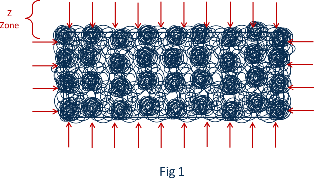
If we mark the boundaries of this crystal piece with a red line, the atoms in the middle row are in contact with other atoms in all directions around them. That is, all their gravitational field is involved with adjacent atoms. In contrast, just the half of gravitational field of atoms on the surface of the crystalline part of a solid or liquid body are associated with their adjacent atoms, and their upper half, at the surface, is relatively free of other gravitational fields.
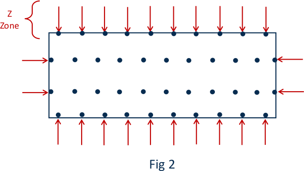
A strong gravitational force with a short range is well known and agreed upon in physics. This is the same force that causes fluid to rise in capillary tubes or mutual absorption of water droplets or mercury pellets to form larger bullets. Therefore, on the surface of all objects, whether opaque, transparent or liquid, there is a strong gravitational zone with a short range, which can be called the gravitational zone (Z-zone) as shown in fig 2.
When we consider light as material particles, in all light phenomena such as light refraction in a transparent environment, light passage through the lenses, the prism or through narrow slits, the direction of the forces the interaction among light particles with the Z-zone is crucial in explaining the same phenomena.
Needless to say, in the direction of the gravitational zone in Z-zone must be perpendicular to the surface. Another thing to note is that this gravitational force gets stronger as we get closer to the surface, and it becomes weaker as we move away from the surface. To have an objective visualization, we assume the height of the Z-area to be approximately 1/1000 mm, which means that at this height on the surface of any solid or liquid there is a strong gravitational force perpendicular to the surface, which consequently effect the material particles of light.
Optical Phenomena:
As mentioned earlier, in all transparent and opaque surfaces and liquids, there is an area that we call the Z-zone. As they approach, they absorb light particles towards themselves and change the path of light. This action of absorbing light particles in the Z-zone of any transparent or opaque surface has important consequences in the phenomena that we will discuss later on. In Fig 3, we show schematically how Z-zone change the direction of light particles
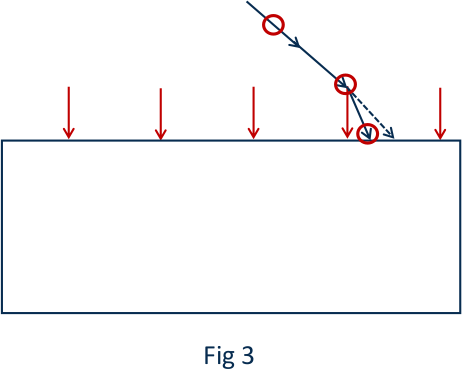
As can be seen in fig. 3, the light particle changes its direction due to the strong gravitational force of the region before reaching the common border of the two transparent regions, and then enters and the transparent environment or is reflected from the surface.
Reflection of light
Assuming that light particles are spherical and elastic material, they tend to reflect when they hit hard material points. Suppose we shine bundle of parallel rays of light (which are, spherical particles of light) on a container full of water. Wherever the light particles hit hard mass points (the nuclei of oxygen and hydrogen atoms) are reflected, and when they hit the free space among water molecules, or through the molecules and between oxygen and hydrogen atoms they will pass through but change direction due to the gravitational forces.
A very simple result of this definition of reflection is that when a beam of light is irradiated on a transparent surface, the amount of light which is reflected is less than amount of light which is refracted. The reason is obvious because in a transparent surface such as water or glass, the atoms that make up the transparent medium are separated from each other and occupy together far less surface than the distance among them. As a result, the amount of reflected light is less than the amount of light passed through (the angle of radiation and the reflection are equal in a vertical line). Fig. 4 illustrates schematically the reflection of a light particle.
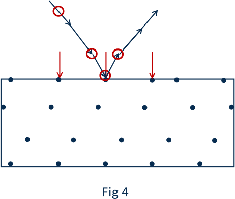
As can be seen from figure 4, when a particle of light reaches Z-zone, its path is changed by the gravitational force of this region and it approaches the vertical line in that region and is reflected after colliding with the surface and moves away. In fact, as the light particle approaches the surface and subsequently moves away from the surface, the forces of the Z region neutralize each other, resulting in the equality of the radiation angle with the reflection angle.
Refraction of light
As mentioned earlier, when a particle of light from air or (vacuum) approaches a clear and dense environment such as water or glass, it is affected by two forces. The first force is the magnitude of the linear motion of the light particle itself and the second is the gravitational force perpendicular to the surface of the transparent medium (the Z-zone) and the future path of the light particle is the result of these two forces as it enters the transparent but more dense environment with a change of direction. The light particle reaches the Z-zone without change of course and the change of direction occurs after reaching the Z-zone and get closer to the vertical line relative to radiation angle. The following figure shows the entry and exit of light particles in a parallel blade of surfaces (Fig 5).
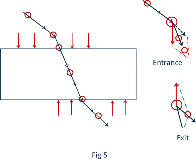
In simpler language, as can be seen from the figure 5, when the light particle enters and leaves the transparent medium, the Z zone pulls the light particle in the direction of its vector and changes it.
When a particle of light enters the transparent medium from the air, the gravity vector Z brings it closer to the vertical line, and the light particle changes its path within the Z zone, before entering the transparent medium, and then enters the transparent medium.
And when leaving a transparent medium, again, and immediately after leaving, it is affected by the vector of the Z zone. As result its direction changes and it moves away from the vertical line.
When a bunch of parallel light rays enters a transparent (dense) medium (such as water or glass), it encounters the gravitational and uniform forces vectors of the atoms in the medium, which naturally act as brakes towards the light rays and reduce the speed of light. The amount of reduction in light speed depends on the density of internal forces in the transparent medium. The path of the light beam goes in a straight line and whenever in its path it collides with existing atoms, light particles can scatter in different directions. Those light particles that do not collide with atoms will leave the transparent environment across their original path.
It is not unreasonable to make a comparison between Newton's theory of light refraction with the proposed theory of Z zone effect: that light particles in the Z zone change direction both when entering a transparent medium and when leaving it.
Newton believed that a particle of light was absorbed by a transparent object and affected by its force. Such forced would inevitably increase the velocity of light particles, argued Newton, which would have resulted in speed higher than speed of light in a vacuum. This erroneous conclusion had dealt an irreparable blow to the particle theory of light.
Whereas in the particle theory of light that we are discussing, the force vector of the Z zone only changes the path of the light particle and has no effect on its speed even in the short distance within the Z zone itself. And opposite to the Newtonian explanation, the velocity is braked and the uniform gravitational forces within the transparent object slow down the velocity of the particle relative to air or vacuum.
The reasons why only the direction and not the speed of light particle is influenced and modified by the gravity of Z zone are as follows:
The origin behind the high speed of the light particles seems to be unknown and is in a way an intrinsic property of all small material particles. The speed of light is the highest known speed known to modern physics, and it is not logical that any other factor can increase such fundamental speed. In other words, such speed cannot be subjected to the laws of Newtonian mechanics.
Perhaps the best argument for the fact that the light particle does not follow the current laws of Newtonian mechanics regarding the acceleration lies in the fact that the speed of the light particle in a transparent medium slows down and immediately after leaving the transparent medium regains its original speed. Which in fact confirms the intrinsic nature of the speed of light particles.
The second reason that can be cited is the fact that the light particle is affected by two Z-vectors at the same time, both during entering as well as leaving the transparent medium. Because the direction of incoming beam is parallel to the outgoing beam, it is necessary that the particle velocity at the time of entry and leaving the transparent medium is equal. Therefore, the conclusion that the Z vector only changes the path of the particle and has no effect on its velocity is a logical conclusion in accordance with what the experiment confirms.
Brief discussion of light reflection and refraction in a transparent environment
Suppose we have a beam of light with a cross-sectional area equal to one square millimeter. While the angle of the light beam to the surface of the transparent medium is small, most fraction of light will be refracted with a tiny fraction being reflected. When the angle gradually increases, the contact surface of the light beam with the transparent medium also increases, with an increasing amount of reflected light and proportionally decreasing intensity of the refracted light in the transparent medium as a result. When the radiation angle is close to 180 degrees, most of the light is reflected and a small part of it is refracted.
Existing theories that consider light as electromagnetic waves are almost silent about the reflection and refraction of light in transparent media and do not have the necessary explicitness about these phenomena.
Light beam leaving the transparent medium and full reflection
As mentioned before, when a light particle enters the air from a dense medium, it exits without any refraction with its direction is perpendicular to the surface. And when the light particle exits with an angle towards the perpendicular line - under the force of the Z zone, it will be absorbed towards the surface and moves away from the vertical line. The larger the angle of radiation, the larger the deflection of the refractive beam from the vertical line, to the extent that it touches the shared surface. It enters the air from a concentrated environment. If we make the radiation angle larger, the light particle will return fully to the concentrated medium due to the maximum gravitational attraction of the Z zone. This is when a full reflection will occur.
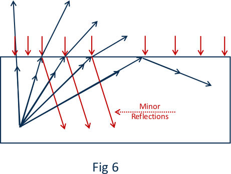
Of course, if we want to investigate full reflection, we must start addressing the partial reflection, that is when the angle is not large enough and just a portion of light is reflected (Fig 6).
A bold prediction
Occurrence of partial reflection of light passing through a transparent (dielectric) medium into the air is according to the theory of the material particle of light a quite simple and interesting event.
According to this theory, when a beam of light enters the air from a clear and angled environment, some light particles collide with the atoms in the air and returns to the transparent environment according to the law of reflection. And in this case, we will have a partial reflection. In case we can place the transparent medium in a vacuum environment, according to this theory, a partial reflection will not occur, and it is likely that the overall reflection will change its nature and angle.
For the author of this article it is impossible to conduct such an experiment due to lack of laboratory facilities. But the author of this paper believes that performing such experiment can be very decisive in confirming the particle theory and the materiality of the light particle. With the hope that such an experiment will one day take place!
The passage of light through a convergent and divergent lens
By considering the gravitational Z vector, which is always perpendicular to the surface of the transparent medium, and the vector of the linear motion of the light particle, which is always along the radius, the path of the beam of light can be calculated and be predicted.
Let examine the standard and best-known examples of convergent and divergent lenses.
The converging Lenses
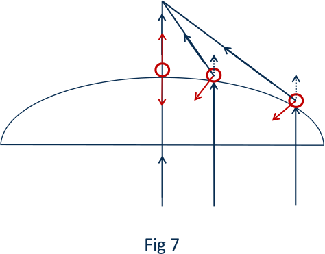
In the following figure of a converging lens, three radii emit parallel to the lens, which intersect after refraction at the center of the lens, along a radius that passes through the optical center of the lens.
Because the direction of the vector Z corresponds to the magnitude of the linear motion of the light particle, it leaves the lens without refraction. Other light rays are refracted proportional to the angle of the gravitational vector Z with the linear motion the light particles. And finally, the light particles accumulate in the center of the lens and the light becomes focal.
Obviously, any ray of light that passes through the center of the lens is in the direction of the Z vector and therefore leaves the lens without refraction.
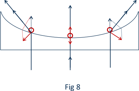
The diverging lenses
When a beam of parallel rays shines on a diverging lens, the cause and the difference in separation of parallel beams can be predicted, ie the closer the parallel light beam to the sides of the lens, the greater the intensity of divergence.
Prism
When a beam of white light comes out of a prism, the light particles are again, under the influence of Z vector and the magnitude of their linear motion, will change direction according to the figure in the prism. Particles of different colors will be separated from each other.
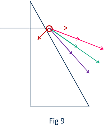
The gravitational force of the Z vector is constant and remains the same, but light particles of different colors are not the same size and have not the same mass. And as a result, the effect of Z force on them will be different. Particles with less mass (and therefore smaller linear motion) will deflect more and particles that have a larger mass (with larger linear motion) will deviate less. From this simple rule it can be concluded that red light particles must have a larger mass than purple and blue light particles. The particles of yellow and green light are lighter than red but have more mass than other colors.
Needless to say, a ray of light separates colors whenever it enters the air from a concentrated medium at a specific angle to the Z vector. If a beam of light shines from the sides of a converging lens, it can create a spectrum of white light like a prism.
Therefore, in the prism, the small angle of refraction of red light is due to the heavier mass of its particle than other lights, and thus it is concluded that from red light to purple light and ultraviolet, the volume of light particles and their mass decreases.
The reasons for the difference in the volume of light particles will be discussed in future discussions.
Light passing through the sides of the opaque body close to the surface
We mentioned earlier that on the surface of all opaque and transparent objects that the outer surface of all such bodies is covered by the Z zone, which absorbs the light particles and modify their path and direction. We also study the effect of these Z-zone forces on the entry and exit of light from transparent environments and saw how light particles enter and exit the transparent environment. We were also able to predict the path of light by plotting the Z-zone vector, always perpendicular to the surface of the transparent object, and the linear motion of the light particle. By discussing the effect of the Z-factor on the linear motion of the light particles we have studied various phenomena such as entering and leaving transparent environments. Also, the refraction of light passing through convex and concave lenses and the prism is referred to in a manner familiar to geometric cognition of light in physics textbooks.
Henceforth we are prepared to consider the phenomena that tend to be discussed within the wave cognition of light. We intend to describe these phenomena by relying on particle theory of light and discussing new predictions. In the first step, we notice the passage of light through the sides of the opaque body and the penetration of light into the geometric shadow of the body.
If we take a thin rod under the sunlight with its shadow on a white screen and gradually move the rod away from the white screen, we find that the shadow of the narrow rod disappears. If we assume that the sun's rays of light can be considered as almost parallel rays of light, the gradual disappearing of the shadow can be explained by the intrusion of light into the geometric shadow of the narrow bar. The cause of this phenomenon is very simple and natural because the light rays that pass through the sides of the narrow bar are deflected by the vectors of their direct path and penetrate the geometric shadow of the narrow bar which eventually means that the shadow disappears. What happens is shown in Fig 10. In simpler language, due to the surface vectors of the Z region, light can bypass small obstacles and light rays can cross behind the obstacle.
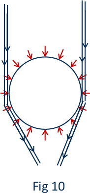
The similarity of this phenomenon is like bypassing the waves of the water pan when it encounters an obstacle.
But in fact, comparing light with water waves is not a good comparison. It goes without saying that in this case we did not consider the collision of light beams with a narrow rod itself and focused our attention on the beams that pass through the sidelines of the rod through its Z-zone. These rays will not collide directly with the narrow rod in any way. In the following sections, we will discuss the collision of light rays with obstacles and diffraction of light or the scattering. Modern physics claims that such can be explained only by relying on wave theory. We will try to address the same phenomena based on the particle theory of light.
Diffraction
The simplest definition for diffraction is the interaction of light particles with the sharp edge of opaque objects. To investigate this interaction, we consider a thin wire to which a bunch of parallel monochromatic ray’s shine which will cause the scattering of light in contact with a thin wire.
When we want to show what happens between light particles near the thin wire in our drawings, we show the light particles as tiny dots. The reader accepts that if we assume light as particles, these particles must be extremely small. We do not have a standard for the weight and volume of light particles, but they should expected to have a low mass and small size, and when we display them as tiny dots, it means that we have magnified them thousands of times. Please also note that the thin wire that is placed in front of the light particles must be drawn as large as possible so that the collision of light particles with the body of the thin wire is more realistic. In figure 11 we have tried to create a schematic representation of the collision of light particles with an opaque object such as a thin wire and show the diffraction of light (scattering of light particles) in this collision (Fig. 11). Of course, in the drawn figure, just a cross section of a thin wire is drawn.

As can be seen from the figure 11, the light that shines on the surface of the thin wire is divided into two distinct parts. The smaller part is reflected at different angles when it strikes the surface atoms of the body because the surface of the solid body is curved and atoms with a parallel beam of light scattered with different angles. The second part of the light is absorbed in the spaces between the atoms of the thin wire.
If you look at the fig 11 closely you will see two simple events can occur in the collision of parallel beams of light with a thin wire:
-
Parallel light rays are reflected after contact with surface atoms into different angles and provide the background for the production of bright bands.
-
In the distances between the surface atoms, the thin wire of light enters the interatomic spaces of the turbid body, absorbing most of it, and provides the ground for the appearance of dark bands.
In other words, light particles that move in a straight after their initial contact with the cylindrical surface of the thin wire are reflected into a much wider surface and scattered. Naturally, the thinner the wire, the smaller the surface and front facing the parallel beams of light, and consequently the angular difference between the reflected beams will be more intense and the incident beams will cause more intense diffraction.
Diffraction of light in a narrow slit
To form a narrow slit with sharp edges, two razor blades can be used, and if we look at the point-shaped light source or a bunch of parallel rays of light from behind this slit, the formation of dark and light bands can be seen. In order to understand what happens when light passes through a gap with sharp edges, we must be able to draw a realistic representation of a gap. In physics books, such gap is drawn with sharp edges as represented in fig 12.

The gap shown above does not correspond to the reality of the interaction of light and the gap. In reality, the light particles are infinite smaller than the edges of the gap and drawing a narrow linear shape means that we have magnified the light particles millions of times. So the sharp edge of the gap must be drawn larger and larger to reveal the reality of the light hitting them.

The real meaning of representation as in figure 13 is that the light particles are so small that any sharp edge of the gap should be represented as a semi-circular surface. This means that this case become like thin wire example that we’ve discussed earlier.
Here, too, light is scattered by colliding with a semicircular surface at different angles, and the light beams are scattered apart and widened as it is approximately presented in the following geometric drawing (figure 14).
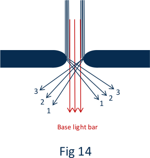
As the figure shows, a parallel beam is divided into three parts when passing through a narrow gap with sharp edges. Some of the beams pass through the gap without colliding with the edges with the same intensity of light (zero degrees) as shown in red rays. The second part hit the sharp edge of the left side and deflect to the right, and in this collision the light particles with the sharp edge of the left rays are separated from each other and real diffraction occurs.
The third part hit the sharp edge at the right side of the gap and deviate to the left and create light diffraction on the left side (and they create light bands 1-2-3 etc)
This is the simplest possible representation of this phenomena with the following conclusions: Light passing through the gap become more open and separated due to the collision of parts of the light beams with the sharp edges of the gap with a result of exceeding the geometric shadow of the gap.
The rays of light that strike the edge of the slit provide light for the reflected bands, and the light that is absorbed by the edges of the slit in the atomic distance provides the background for the dark bands. The beams that pass through the middle of the gap and do not touch the edges travel their straight path without any change and form the bright part of the zero region.
A simple experiment
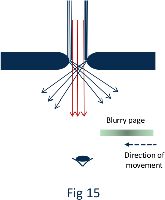
If we look from behind a slit to diffuse bunch of parallel rays, we will see dark and light stripes on the sides (zero point). We can place a blurred sheet of paper between the observing eye and the gap. When we approach the gap on the right, the opaque screen is slowly approaching the gap, the first place that will be dark and the light does not enter the eye is the sharp edge from the left, and whenever we repeat this experiment and approach the gap from the left, the first place to darken will be the sharp edge on the right side of the gap.
This test confirms that the dark and light bands on the right originate from the left edge of the gap and the dark and light bands on the left originates from the right edge of the gap (Fig 15).
So far, we have discussed the simplest form of diffraction, while the most complete form of diffraction occurs when we consider the gravitational force of the Z zone and its effect on the path of light particles. The experiment also confirms that the closer the distance between the two edges of the gap is, the more the rays of light passing through the gap widened and the more diffraction occurs. This phenomenon can be understood and justified only by having the gravitational force of the Z region at the edges of the gap. By drawing a figure 16, we try to describe what happens to light particles
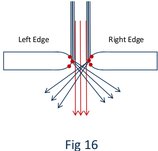
As can be seen from the figure 16, the light rays that hit the left edge of the slit, when passing through the Z-zone on the right edge, attract the gravitational effect of this Z-zone towards the light particles and intensify its deflection, and so on for the light particles which hit the edge of the gap on the right side and wants to pass through the Z-zone of the left edge.
This gravitational effect makes the separation of dark and light bands clearer and more profound. At first, claiming that light particles collide with an edge and pass through its gravitational Z zone to create the dark and light bands at the opposite site of the edge may not be easily accepted, but this claim can be proved by arranging a simple experiment.
The order of the experiment is that we have a narrow gap and a bunch of parallel monochromatic rays. Whenever we look at the rays of light from behind this gap, dark and light bands are visible on both sides of the gap. When the sharp edge at the right side is gradually moving a few millimeters towards the source of light, the dark and light bands at the right side will become less visible, while the dark and light bands at the left side remains visible. Such observation can be explained by drawing figure 17.
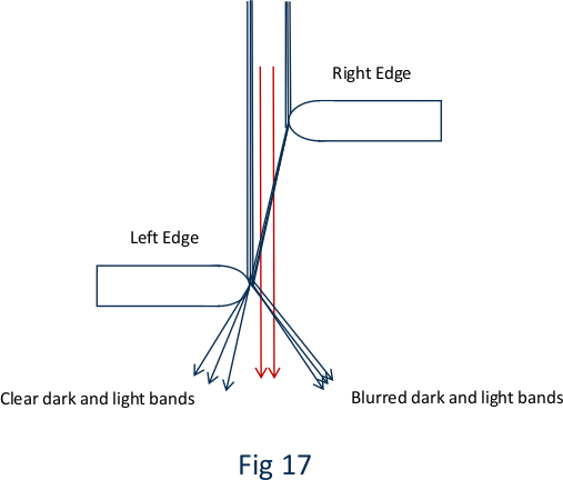
As can be seen from the figure 17, the light beams that hit the sharp edge at the right side pass through the Z-zone gravitational field of the left edge in their deviation, and due to the gravity of this Z field, the clarity of dark and light bands increases. Z-zone widens the dark and light bands and increases their sharpness, while the diffracted rays at the left side do not pass through the sharp edge at the right side, resulting in less sharpness and fading dark and light bands at the right side.
Another thing to note is that as light passes through a narrow slit, the narrower the slit, the more diffraction and widening of the light. This phenomenon can be explained and be predicted by considering the gravitational Z-zone and the rays reflected from the opposite slit edges to the opposite side.
The closer the two slit edges are to each other, the larger proportion of the diffracted light particles become strongly affected by the gravitational field of the opposite edge and the more they open from each other.
Another thing to note is that as the edges of the diffraction gap get closer together, the intensity of the zero-zone light decreases to the point where the zero-zone light disappears altogether, leaving only the right and left diffraction.
Diffraction grid
Diffraction grating is the placement of very sharp edges together that cause diffraction and intense scattering of light and separation of different light particles (different colors) from each other. In fact, diffraction grid can experience light by reflecting incoming light on It is diffracted on the sharp edges of the grid.
Disintegration of white light
As mentioned before, spherical, and elastic particles of different colors of light have different masses and diameters, and this difference in the mass and diameter of light particles causes separation and decomposition of light in both the prism and the grid.
As a reminder, we first mention how light decomposes in the prism and then we deal with the phenomenon of light decomposition by the diffraction grid.
Decomposition of light in prism
When a narrow beam of light exits an orthogonal prism, under the influence of gravitational force vectors Z, and proportional to the mass difference of light particles, the refractive angles of different lights will be different from each other.
The lower the mass of the light particle, the greater the degree of deflection and refraction angle. So we conclude that red light particles have more mass than other mass particles and purple light particles in the visible spectrum have a smaller mass light, therefore the lowest angle in the analysis of white light in the prism will belong to the red light, while the purple light will have the highest angle of refraction relative to the direction of white light. In other words, the difference in mass of light particles is the main source of light separation (Fig 18).
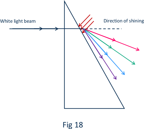
In confirmation that red light particles have a heavier mass, we refer to the fact that experiments have confirmed that the speed of red light in dense environments such as water and glass is slightly faster than other lights, and this fact is consistent with the larger linear motion of red light particles (ie, the mass of red light particles is larger than the mass of other visible light).
In short, we remember that in scattering prisms, the difference in mass of light particles against the gravitational force of Z-zone causes a difference in the amount of deflection (refraction) and as a result causes the decomposition of white light. Purple light will have the greatest angle of deflection relative to the direction of white light emitted to the prism.
Diffraction grid & decomposition of light
Contrary to the prism that the refraction of light determines decomposition of light, in a diffraction grid, the reflection of light particles from sharp edges and the difference in reflection of light particles with different diameters create light decomposition.
The reflection law’s involving a ray of light and a flat surface are well known (the angle of radiation and the angle of reflection are equal, and in the case of spherical mirrors the laws of radiation and reflection of light are valid as long as their surface is small and the curvature of the mirror is not sharp). But if the light particles are elastic and spherical with different diameters for different colors when dealing with circular surfaces with small diameters (such as a very thin wire or the sharp edges of a slit or sharp edges in diffraction grid), light particles with different diameters will have different angles of reflection along the incident light.
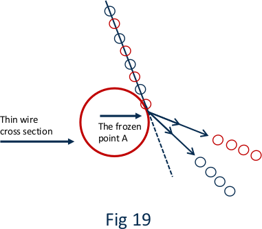
In Figure 19, an example of a thin wire is presented. Different light particles (for example red and purple light) shine at point A. These light particles have different diameters and their angle of reflection will also be different, meaning that red light particles that are larger in diameter will have a larger angle of reflection than the emitted ray, and purple light particles that are smaller in diameter will have a smaller diameter than the incident ray and create smaller reflection angles, resulting in the separation and refraction of light.
Therefore, in the separation of different colors on a diffraction grid, the difference in the diameter of light particles reflected from the circular surfaces plays a decisive role.
Comparison of light decomposition in the prism and diffraction grid
As mentioned, the reason for the decomposition of white light in the prism is the difference in mass of light particles and the effect of the Z-zone of the prism surface on light particles. Heavier particles will show the least deflection while the purple light particles find the most deflection (due to their lighter mass).
Needless to say, our discussion focuses on the visible light spectrum and particles of the visible spectrum. But the decomposition light based on particle mass difference goes beyond visible spectrum and remains explicable and predictable in any spectrum.
Thin shells and decomposition of white light
Thin shells, such as soap bubbles or thin layers of oil on the surface of water or wet asphalt, decompose light in an interesting way. The repositioning of molecules such as soap scum or fats in the form of a thin layer on the surface of the water lay the formation of a diffraction grid, resulting the possibility of observing different colors from different angles.
A reference to the wave theory of light and the problem of diffraction
To justify the phenomenon of diffraction and the formation of dark and light bands whose location is constant relative to time, by the wave theory of light (transverse waves), one principal condition should be met. This basic condition lies in the fact that all the train of waves that reach and pass through the edges of the gap must be in equal phase of oscillation with each other. Such basic condition is required to enable waves to differentiate their path in terms of λ or λ/2 to light and dark strips. This condition is never met on a natural source of light like a tungsten lamp. Such condition can only be met in case of a laser light but not most natural light sources.
Another question that can be asked, is how the phenomenon of diffraction of light and separation of dark and light bands 1, 2 and 3 occur based on the wave theory, assuming a mono color and parallel light is shone into a gap. It is interesting to ask how the difference between creating dark and light bands in rows 1, 2, 3, etc. occurs while the gap conditions remain constant.
Polarized light
Natural light is divided into three basic components when passing through transparent environments: 1) the part that is reflected, 2) the part that refracts and 3) the part that absorbs into the atoms of the transparent environment. But in the case of opaque objects, the interaction of light with the object includes reflection (proportional to the color of the opaque object) and absorption.
Definition of a homogeneous light based on particle theory of light
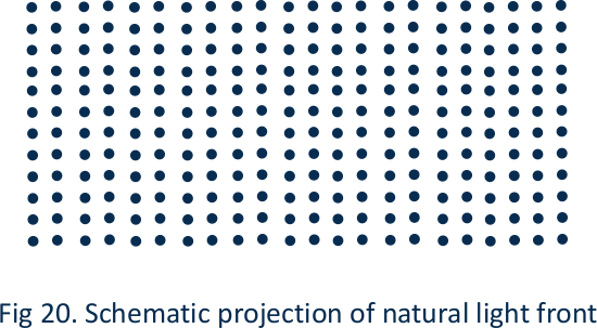
A natural light front is material light particles that are regularly placed next to each other with no difference or advantage in any direction of space according to the figure shown below.
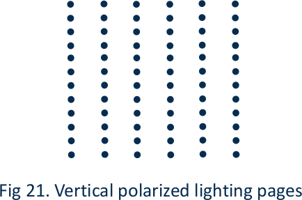
Polarized light
Polarized light consists of surfaces of natural light with defined and equal distance among them (each surface is composed of light particles). These surfaces are parallel to each other and can take any angle from zero to 90 degrees with respect to the direction of light propagation.

One of the simplest methods of producing polarized light is to reflect light from transparent surfaces at a suitable angle, for example, a reflected light from the glass surface is polarized at an angle of 57 degrees (Figure 23).

In this experiment, the natural light front AB strikes the glass (polarizer) at point B. Most of the light is refracted, part is reflected, and part is absorbed by the glass. The reflected light BC is polarized. The glass at the bottom (analyzer) reflects the polarized light (if it is parallel to the top glass) and if the analyzer glass gradually rotates to 90 degree in respect to its initial parallel mode, the reflected polarized light reaches zero.
In fact, it can be concluded that in this case all the polarized light is absorbed and reduces the light intensity to zero. In glass (polarizer), ie point B, the angle of natural light (57 degree) is also important to create polarized light. This angle plays an important role in the amount of light that must be absorbed. In other words, the reflected light divides into polarized light and absorbed light at this particular angle is.
In this experiment, the important point is that the light shining on the glass removes most of the light by breaking it in the glass and the natural light front is transformed into plates of light particles at a distance from each other, and these plates are called polarized light particles. If we use a mirror instead of glass, that is, almost all the light is reflected, we will not have polarized light.
Another method of producing polarized light is the passage of natural light through the polaroid plates. In this method, a larger share of natural light is absorbed in the polarizing plane and part of the natural light that is emitted is polarized. The light is fully absorbed and reduced to zero when two planes are perpendicular to each other is. When the two planes are in parallel position the polarized light is passing through.
Smooth passage of two rays of light through each other
In standard physics books, it is claimed that two rays of light, no matter how high the intensity of light can pass through each other without affecting each other, a claim which then often used to reject the wave notion of light. Of course, there is no detailed mention of the scope of this experiment and how it is performed exactly, but we seriously doubt the accuracy of this claim because if our assumption is focused on normal light particles and we accept the test conditions in such a way that two rays of light passing through each not once but in high repetition, the collision of light particles will inevitably be shown with consequent damage to their light beams.
A simple experiment
Hold 40 to 30 microscope slides between your thumb and forefinger and look at a light bulb behind this number of slides. The image of the bulb is completely blurred with an obvious reason.
Because by passing the assumed number of 40 slides, light beams will pass and reflected many times. A part of the transmitting light of the luminous lamp is reflected every single time and the particles of the transmitting light and the reflected light particles collide with each other, creating a blurry image of the luminous lamp. When the reflected light is not disturbing the passing rays of the lamp, the image of the lamp will become clear and bright. In this case the light passed through the slides is completely polarized. This simple experiment could be the reason why light particles are able to interfere with the passage of opposite particles and damage it.
Atomic structure of matter
The atomic structure of matter means that the granularity of different elements and different materials seems definite. Basically, all materials, whether heat and light particles and other particles such as alpha and gamma particles, X particles and elementary particles, all have the property of being granular and participate in the atomic structure of matter according to the A & B principle, ie as long as they are in a composition with other atoms, their physical and chemical properties are hidden and latent, and whenever these particles are released from the atomic body of matter for any reason, they will show their intrinsic, physical and chemical properties.
To simplify the discussion, we assume that the basic framework of the atomic structure of various elements consists of three particles, ie the sharing of protons, neutrons, electrons, and take the participation of other particles such as elementary particles, heat and light particles, etc. in the atomic structure as trivial and insignificant.
Theoretical physics assume atoms with positively charged elements in nuclei that include protons and neutrons and the presence of negatively charged electrons in proportion to the number of positive charges of the nucleus around the nucleus in various constantly moving circuits (Bohr atomic model).
This atomic model contradicts all known standards of physics, and in short, this atomic model is not defensible. A few drawbacks of this atomic model are summarized here:
-
The accumulation of positively charged particles in the nucleus of an atom that must normally repel each other is not acceptable for the cohesion and strength of the nucleus as the main part of the atomic structure.
-
The circulation of electrons with negative electric charge around the nucleus in different orbits at extremely high speeds without the collision of these particles with each other and without interference with adjacent atoms can be one of the strangest assumptions of contemporary physics.
-
The current state of physics claims that the rapid motion of a charged particle must be accompanied by the emission of radiation waves but ignores this in case of the circulation of electrons in the rays around the nucleus.
The structural idea behind this atomic model seem to be derived from a false principle, which is the principle of charge conservation. What does the principle of charge conservation mean and how should it be imagined? There is no significant discussion in physics textbooks about this principle and its quantity, and based on its meaning (charge conservation), one should expect a charged particle (either a negatively charged particle or a positively charged particle), whether free or involved in the structure of matter, will exert its negative or positive charge, and this ability is an integral part of the property of a charged particle, and only when the number of negative and positive charged particles are equal in matter, charge neutrality can be measured.
This claim will be acceptable when it is confirmed by various physical phenomena and no violation of this principle is seen in practice. Perhaps the simplest example of our information is the reactions of radioactive materials, in most of which radioactive materials like positively charged α particles or negatively charged β particles are irradiated from the nucleus of radioactive materials without changing the electric charge balance of the radioactive material itself which is always electrically neutral. And in addition to this, radiating negative particles from nucleus with a significant positive charge are far from sound physical logic.
Another thing that contradicts with the principle of charge conservation is the production of X-rays. We know that X-rays are obtained by the collision of accelerated electrons (cathodic rays) with a hard metal such as tungsten. But here we ask the following question: when electron particles with negative charge and high acceleration are injected toward a piece of tungsten metal, a lot of heat and X-rays are produced. But how is het possible that the initial step in this process itself will not prevent additional electrons with negative charges from approaching towards the tungsten metal piece?
The initial layer of electron will change the charge of metal piece and preventing the rest of negatively charged electrons to leave the cathode and accelerate without charge of their charge property?
Other examples can be given in this regard, for example in photoelectric cells, the release of many electrons from the metal surface that is exposed to light radiation, the neutral electrical balance of the metal surface is not disturbed and as long as the difference between potential and light radiation continues. Electrons also exit the metal surface. Another example is the generation of current in an induction coil. If we take measures to keep the direct current electrons in the induction coil out of the circuit somehow, no matter how long this process continues, it will be neutralized in the experiment. The title coil will be low, and the cassette will remain. The result, however, is that the principle of load conservation is not defensible.
Atomic structure of matter according to the principle of A & B
The simple principle of A & B defines the atomic structure of elements in such a way that, as mentioned before, when material particles participate in a formation with other atomic elements, their physical as well as chemical properties come out in a dormant state and remain so until they are re-released. It is amazingly simple and natural to accept that having a negative or positive charge is one of the physical properties of the particle. And according to the A & B principle, charge conservation loses its meaning. According to the A & B principle the charge property of a particle will remain hidden until it is re-released (for whatever reason). Accepting this simple principle solves the problem of negatively and positively charged particles being together and can visualize their behavior without strange modeling of the atomic structure of the elements.
In simple terms, if you consider a copper atom, thousands of electrons can be located next to the nucleus of the copper atom in the vicinity of neutrons and protons of the copper nucleus, or even in the nucleus besides the neutrons and protons, participating in the metal structure but do not interfering directly with each other. These electron and proton particles will show their positive or negative charge as soon as they are released from the bond of the copper atom.
The best reason for the above claim is the production of different types of elementary particles in the collision of accelerated particles with different elements. After collision, the identity of elementary particles and their properties such as the presence of charge, whether positive or negative or neutral. Will present their selves. This definition of charged particles makes it extremely easy to understand many physical events. For example, the generation of static electricity by friction means that electrons are detached from the atomic body of matter and released. And by being released, their physical charge properties become instantly visible (at the same time heat particles are also released by rubbing and friction).
All physical phenomena can be explained by considering that light and heat are composed of material particles and have high velocities. For example, in the photoelectric phenomenon, light material particles can collide and penetrate the metal surface and by creating friction remove electrons from the metal body creating a weak current or generates heat in the thermoelectric phenomenon.
It is not unreasonable to speak once again of the value, simplicity, and generality of the A & B principle. This principle on the interactions of material particles is astonishingly simple but effective in explaining most fundamental physical observations. To our view natural events should be explained in the simplest and shortest way possible, as there is no need to use unjustified complex methods to explain natural phenomena.
Application of the A & B principle in the bombardment of matter by accelerated particles
As mentioned earlier, in the bombardment of atoms of different materials, different elementary particles reveal their identities, which can be determined by different methods according to the A & B principle of particles.
These particles with a variety of properties (positive charge - neutral negative charge) can participate in the structure of matter and their properties are kept hidden and silent in the matter of elements and when these particles are released and open their physical identity, their properties can be observed. In contrast, the experiment confirms that the independent lifespan of most of these particles is short and they quickly disappear from the test medium by being so-called disintegrating.
This form of perception, the disintegration of the elementary particles which states destruction of material particles, conflicts with the principle of mass conservation.
the A & B principle of particles states that instead of being disintegrated, these free particles combine quickly and regain their latent physical and chemical properties in combination with their nearby materials which makes them hidden from direct observation.
A brief discussion on magnetism
Magnetic force (magnetism) and the creation of a magnetic field always remain questionable and unsolved in contemporary theoretical physics, while it is quite possible to explain and justify magnetism with the theory of material particles which states that the nature of magnetism is particles material with an intrinsic spin.
The behavior of these material particles is again consistent with the principle of A & B in that magnetic particles which participate in a composition and are not free, have latent magnetic properties and when magnetic particles are free their physical properties become visible and observable.
It can be said that magnetic particles are one of the material particles of nature with amazing properties. These particles are characterized by extraordinarily strong intrinsic spin. The intrinsic spin of these particles when interacting with other magnetic particles can generate a repulsive or gravitational force.
To better understand and visualize magnetic particles and how to attract and repel at the poles of magnets, we try to show this principal by the following drawing. If a magnetic particle can be represented in large its spin can be represented as follow:
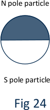
Now suppose we look at the N pole of a magnetic particle from the front with a clockwise spin, and the S pole with a counterclockwise spin. For the convenience of the discussion, we call the N spin the “base spin” and the S the “opposite spin”
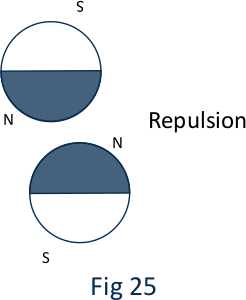
Conversely, if we visualize that the N pole of a particle with a base spin is facing N pole of another particle, these two poles with base spin have the opposite direction of motion (or spin) and they will repel each other, like presented in figure 25.
if we visualize that the pole of a N particle with a base spin is facing to the pole of a S particle with an opposite spin, these two poles will have the same direction of motion (or spin) and they will attracting each other, like presented in figure 26.

If we assume that we have a blade-shaped magnet, the magnetic particles accumulate at the two ends of the blade magnet as presented in figure 27. It goes without saying that why magnetic particles tend to accumulate in iron and steel is truly one of the secrets of creation and there is no good reason for it.

In a permanent magnet blade, magnetic particles are located permanently at both ends of the steel blade, and do not combine with the permanent magnet blade (Fig. 27).
It is not inappropriate to consider how electricity is generated when a copper coil rotates within a magnetic field of a magnet.
Experiments confirm that magnetic force passes through all materials and objects. It comes in contact and friction with the material body of the copper coil and separates and releases the extinct and latent electrons in the copper coil, resulting in the movement of the released electrons to form an electric current.
A separate category called energy
Whenever we can explain phenomena such as heat, light, electricity and magnetism by the existence of material mass particles and define their various properties by material mass particles, then we realize that a separate category called energy and the principle of energy conservation is losing its physical meaning. Phenomena like heat or light can be explained in relation to the principle of mass conservation which ultimately means that there is no such thing as the equivalence of matter and energy.
The ancient idea that once wanted to explain all phenomena with matter and motion is revived and explaining the observed universe in the simplest possible way, by only using matter and motion. Everything, the entire universe is built entirely on mass and nothing more. This should be the first and the most fundamental principle of theoretical physics and the physical law of A & B will complement it.